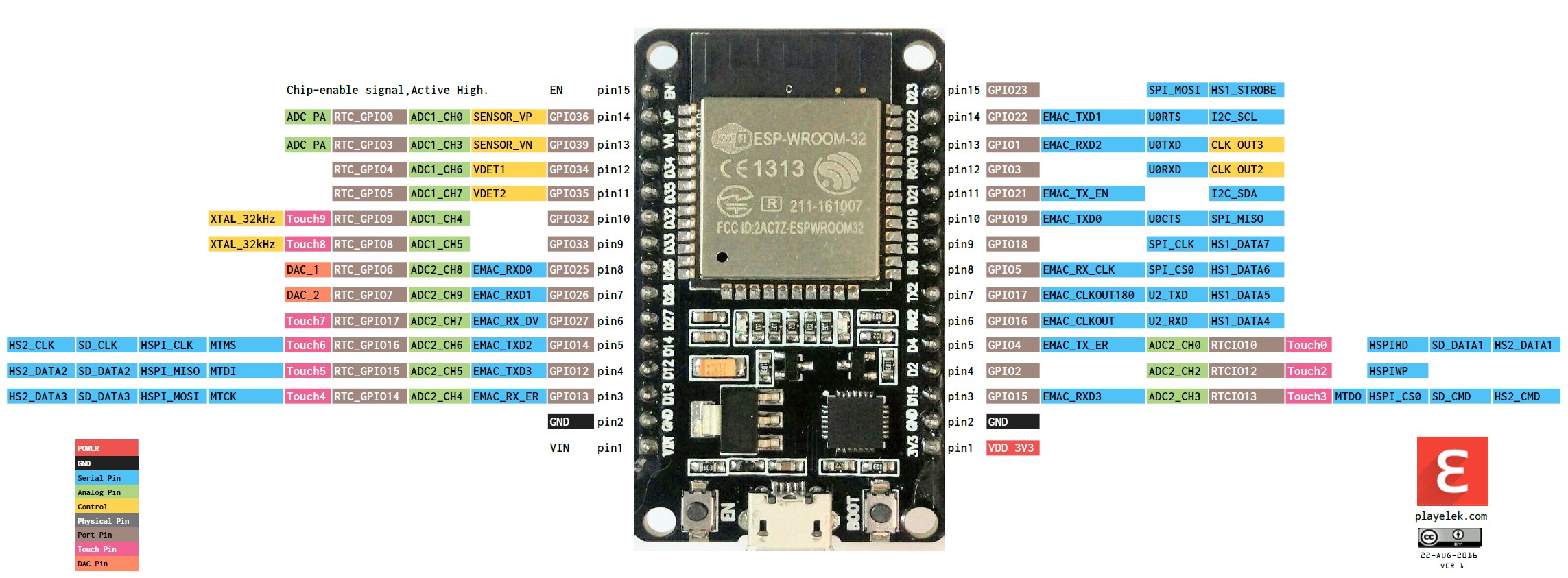
SD CARD I/O PINS
SCK (Serial Clock)
MOSI (Master Out Slave In) -> card
MISO (Data in) <- card. [ ergo can use any GPIO > 33 and save an i/o pin! ]
CS or SS (Chip select)
VCC
GND
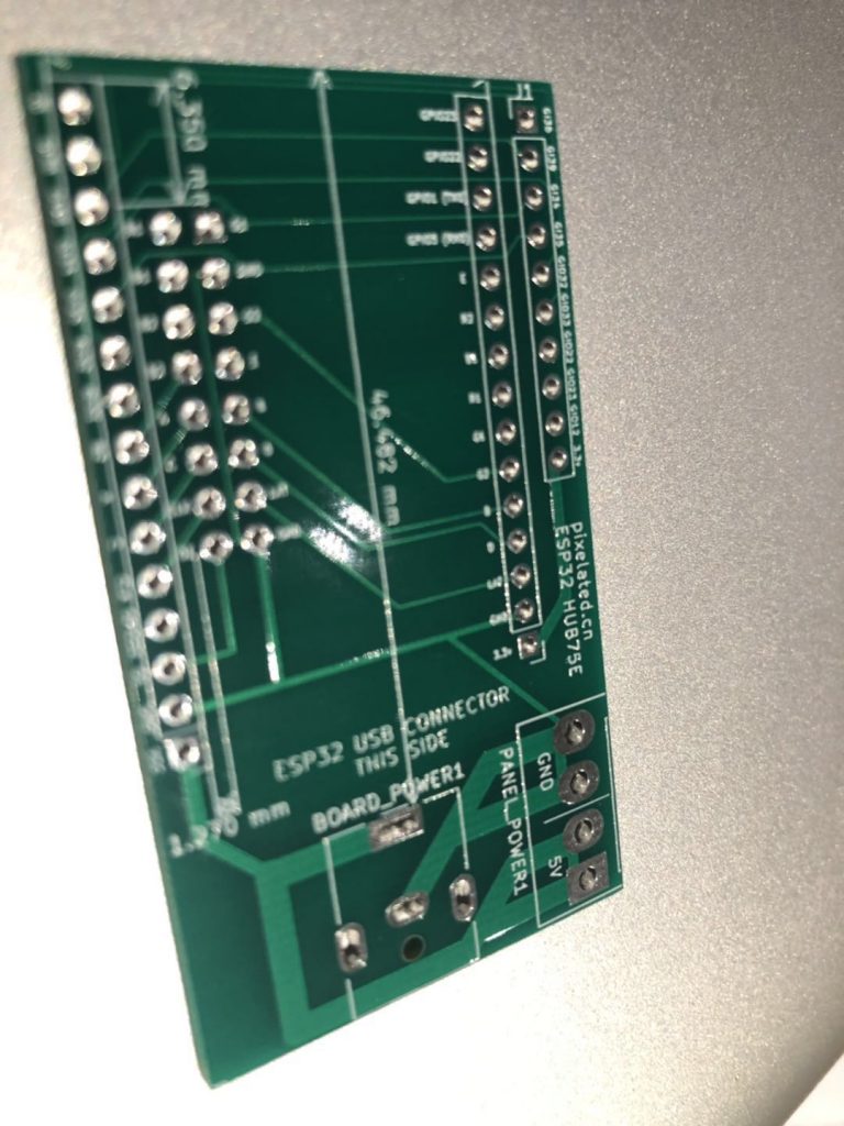
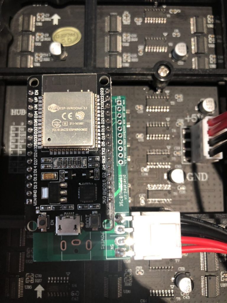
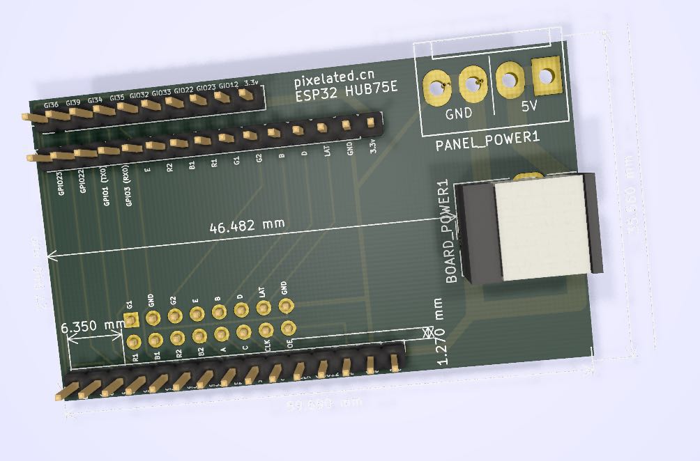
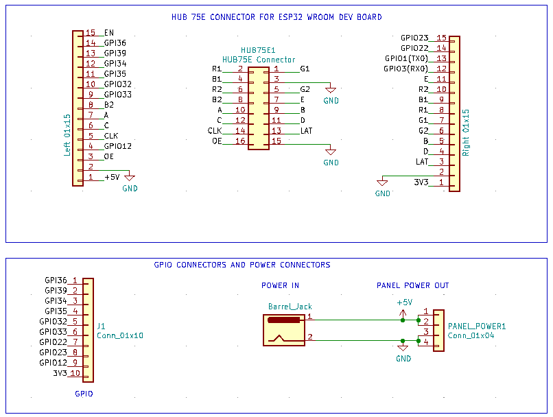
Board Pins
SPI pins – 4 needed, [3 I/O, 1 input]
Available –
GPIO22,23, 32, 33, 12 (12 see notes)
GPI 34,35,36,39
https://github.com/espressif/esp-idf/blob/master/examples/storage/sd_card/main/sd_card_example_main.c
// Pin mapping when using SPI mode.
// With this mapping, SD card can be used both in SPI and 1-line SD mode.
// Note that a pull-up on CS line is required in SD mode.
#define USE_SPI_MODE
#ifdef USE_SPI_MODE
// Pin mapping when using SPI mode.
// With this mapping, SD card can be used both in SPI and 1-line SD mode.
// Note that a pull-up on CS line is required in SD mode.
#define PIN_NUM_MISO 35
#define PIN_NUM_MOSI 22
#define PIN_NUM_CLK  23
#define PIN_NUM_CS   32  //Needs 10k pullup resistor??
#endif //USE_SPI_MODE

SPI.begin(PIN_NUM_CLK ,PIN_NUM_MISO ,PIN_NUM_MOSI,PIN_NUM_CS ); //sck, miso,  mosi,  ss
SD.begin(PIN_NUM_CS, SPI, 24000000, "/sd"));
...